|
Adding the
Front Locker
 If
you have any other questions about the locker, feel free to send
me a personal
email. Also don't hesitate to contact Powertrax
or your local Powertrax dealer for application information. The
Powertrax No-Slip has been manufactured to fit many rear ends, including
some limited slip applications. If
you have any other questions about the locker, feel free to send
me a personal
email. Also don't hesitate to contact Powertrax
or your local Powertrax dealer for application information. The
Powertrax No-Slip has been manufactured to fit many rear ends, including
some limited slip applications.
Shortly after
I installed the rear locker and took it out on the trail a few times,
I became addicted to traction. With each outting I found myself
attempting more and more gravity-defying feats in my moderately-equipped
TJ. There was no stopping me, and I have the dents and dings to
show for it.
Every now and
then, I'd encounter a steep rock ledge, or some kind of terrain
that my locked rear axle was unable to push my open front axle up
on to. I'm sure all of you know what it feels like to be stopped
by terrain that you just know in your gut that you could have made
it if you had adjusted your line a little... or if you had a front
locker.
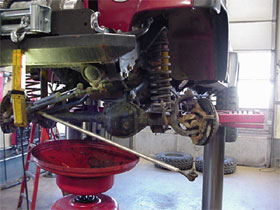 |
| You'll want to get
your tie rod out of the way. Unbolt it from the spindle,
give it a good smack on the knuckle with a hammer, and
the tie rod end should drop right out. |
|
Front
End Concerns:
Never having been equipped with a front locker before, I had
a couple of concerns which were as follows:
- Will
my Jeep still be tolerable as a daily driver with the addition
of the Powertrax No-Slip front locker?
- Not
being much of a mechanic, will I be able to install it myself
as easily as the rear locker?
My questions
were answered soon enough, because my locker was on the way,
whether I was ready to tackle it or not. First, I combed the
web for answers to these two questions. They were answered,
but not to my satisfaction. After some searching, did manage
to piece together enough information about the install.
|
From the information
I pieced together, I found out that most people had tried to install
front spider gear replacement lockers on late-model Jeep Wranglers,
and they had encountered a problem where the cross shaft interfered
with the ring gear. This means the ring gear needed to be removed
to complete the installation successfully, which also meant that
the whole carrier must be removed from the housing.
|
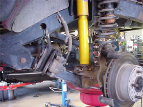
Remove
the Diff. Cover and Inspect
The first thing that needed to be done after the tie rod was
hanging out of the way, was to move the differential cover
and examine my setup. That would tell me exactly what I was
in for in an instant.
I did
just that, and after admiring the apparent dirtiness of my
gear oil, I turned the carrier and noticed that, indeed, the
removal of the cross shaft would be obstructed by my ring
gear.
Again,
this is a 1999 Jeep Wrangler TJ with a stock 3.73 gear ratio.
The ring gear is too thick and impedes progress.
Now that
I removed the differential cover, I knew what had to be done,
so it was time to slide the axle shafts out. This is necessary
in order to remove the entire carrier, and to install the
locker. Once the locker is installed, and the carrier re-installed,
the axle shafts can be slid back in.
|
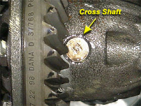 |
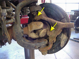
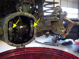
| You can see the
problem as clear as day in this picture. For those who
don't know what youre looking at, this is the ring gear
on the carrier behind the differential cover. The circle
in the center is the cross shaft which needs to come out
to install the locker. As you can see, the teeth on the
ring gear block it from sliding out. |
|
 |
| Brake calipers are
hanging out of the way and we're one step away from sliding
the axles out. |
|
The first
step to sliding the axles out would be to disconnect the brake
calipers. You don't need to disconnect any brake lines, just
unbolt the calipers from the rotors. Just a quick warning
- be very careful to not cross-thread the caliper bolts when
putting them back in later (what a pain in the butt that was)!
Hang the
calipers out of the way using a wire or bungee cords. Once
that is done, the rotors should be able to slide off easily.
Put them down on the floor.
Also,
don't let anyone accidentally press your brake pedal while
the calipers are off the rotors. If they're left alone, they
should slide back on over the rotors easily when you are done.
|
 |
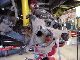
| Two of the three
bolts needed to disconnect the axle shaft assembly from
the spindle can be seen above. |
|
 |
| In the picture above,
the rotor and shield are still attached - this is not
necessary. |
|
Remove the
Axles
On the back of the spindle, there are three bolts around the axle
u-joint. You can see two of them in the picture above and to the
left. The third is obscured on the other side of the axle shaft.
These three bolts attached the sealed wheel bearing assembly to
the spindle. The axle is secured to the wheel bearing assembly,
so when the bolts are removed, you can slide the whole assembly
out in one piece.
 |
| The axles are removed
from each side. It is possible that your axle tubes are
very dirty on the inside. I recommend cleaning them out
thoroughly before re-installing. |
|
 |
| Inside the rear,
on the left and the right side, you can see the bearing
caps. These must come off, but you must remember their
exact position to ensure proper wear. |
|
Pull the
Carrier
Once the axles are out of the way, you're ready to pull the carrier
out of the housing and set it on the bench. This is the only really
critical step that I was instructed to pay close attention to. On
the inside of the differential, on the left and right side, there
are two arcs that are bolted down. These are bearing caps. You need
to remember how they are positioned when you remove them so you
can re-assemble them the same way.
By re-installing
them in the same position they were un-installed, you ensure that
you are not changing any tolerances that would affect how the bearing
wears underneath. Mark them and put them in a safe place while you
work.
When the bearing
caps are removed, the carrier will most-likely roll right out. If
it resists, you may have to pry it out with a pry bar, in which
case, be careful not to damage anything. The carrier is the assembly
on which the ring gear is mounted and the spider gears are contained
within. On each end there will be a race that seats a bearing. Pull
off each race. Again, keep track of their position so they get put
back in the same position.
|
Tearing
Down the Carrier
At this point, we're done working under the Jeep and we can
continue our work on the bench. The carrier in which we install
the Powertrax No-Slip is now seperate from the vehicle. Next,
we unbolted the ring gear by securing the carrier in a bench
vice and turning each bolt out one by one. You'll need your
Popeye arm for this. Once each bolt was out, we marked where
the ring gear was seated on the carrier so we could put it
back the same way.
The ring
gear wasn't bolted down, however, it is still tightly seated
on the carrier. It took some prying to remove it. Once we
had it off, we cleaned it and set it aside.
Now it
was time to remove the spider gears. This was the last thing
we had to dis-assemble before we could begin re-assembly with
the Powertrax No-Slip.
|
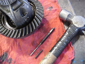 |
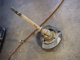
| Pictured here is
the carrier with the ring gear still on it. Also, a hammer,
a punch, and the roll pin that holds the cross shaft in
can be seen here. The roll pin is out and between the
punch and the hammer. |
|
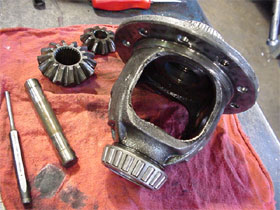 |
| An empty Dana 30
carrier awaiting the installation of a Powertrax No-Slip
Traction System. |
|
The roll
pin caught us off-guard. I had been used to working on my
Dana 35, which uses a retaining bolt to hold the cross shaft
in, not a roll pin. Not having worked with it before, I didn't
know exactly how it liked to come out, nor did I know how
much force to exert on it.
I tracked
down the proper tools, pictured above, and tapped it out with
only very mild force. Once the roll pin or retaining bolt
is out, the spider gears practically tumble right out.
Take the
old cross shaft, spider gears, side gears, and all related
thrust washers and put them in a box and take them with you
to your next swap meet. Who knows, someone might need them
on the trail. You won't need to re-install them.
|
Page
3 (Install and Test the Powertrax) --->>>
|